

This is reproduced here from the website of Dave Cushman G8MZY www.dave-cushman.net
Hexalator is a trade name of TDK, for a type of circulator composed of microwave ferrites, mesh like centre conductors and magnets.
The first hexalator... I am not sure of the date, but I remember the occasion! Jack Bennett G3PVG announced that he had obtained the device, while several of us were on our morning trip to work (in QSO, probably on S0). It obviously made a big impression on me, as I can even remember the exact piece of road that I was driving along at the time.
The second hexalator was built by myself, from parts provided, or paid for, by LRG. In essence it was a die cast box with three "N" type connectors for the signal cables and three BNC type connectors for resistive, filtered diode probes that were permanently connected to the main signal lines. This method gives good stability as making test connections has little or no effect on the impedance of the signal lines themselves. The connections from the Hexalator to the trimmers and the "N" type connectors were by means of double sided PCB microstriplines sized and shaped to suit the expected impedances at every point in the system. Finally each of the three identical sections were screened from each other by pieces of double sided pcb material soldered up to form enclosing boxes with holes to allow for trimming tool insertion. Captive dust caps were provided to cover the BNCs when they were not in use.
Hexalator dimensions:
| Parameter | CU 331A | CU 322A |
|---|---|---|
| A | 7 | 7 |
| B | 6 | 6 |
| C | 12 | 15 |
| D | 14 | 17 |
| E | 0.5 | 0.5 |
| F | 0.5 | 0.5 |
| G | 3 | 3 |
| H | 13.5 | 13.5 |
| PCD | 30 | 38 |
All dimensions in mm .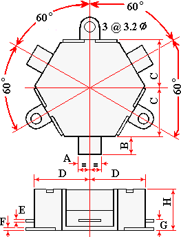
The connection tab thickness seemed to be thinner, and the tab shorter, than the table indicates.
The TDK specification sheet shows the upper limit of the CU 322A as 400 MHz... The actual device used had been specially selected, by testing from a production batch, for use at 432 MHz.
Schematic of the original unit
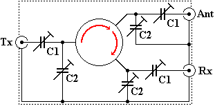
Circulator = CU 331A
C1 = 3 pf to 7 pf
C2 = 5 pf to 9 pf
Connectors = BNC
Isolation greater than 20 db
insertion loss less than 1 db
Schematic of the completed new unit for MK2.
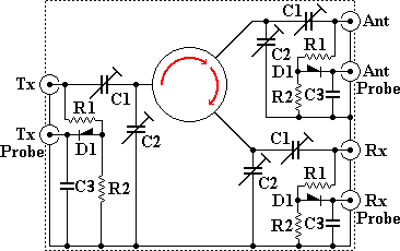
Circulator = CU 322A
C1 = ?? pf to ?? pf
C2 = ?? pf to ?? pf
R1 = ??
R2 = ??
D1 = ??
C3 = 0.01µf monolithic
Line Connectors = N type
Probe Connectors = BNC
The parts list has not been completed, as the details were passed to the next GB3LE project engineer... From memory, I reckon C1 and C2 were 4 - 10 pf, R1 and R2 were 51 R and the diodes were 1N 918. I hope these details will come to light later.
PCB dimensions
I have the drilling jig that I made for the PCB, but cannot find it at present.
Physical appearance of MK2 hexalator
At some point the cavities were replaced by a 'block filter'. I do not think this required an aerial circulator.
My memory is far from perfect, corrections and additional details are welcome and are actively sought.
{backbutton}
This is reproduced here from the website of Dave Cushman G8MZY www.dave-cushman.net
The first aerial used for testing and I believe, the first few weeks of actual operation, was a Cushcraft ringo ranger AR 430 that had been optimised for working on RB4.
The first 'permanent' aerial was set of four folded dipoles that were intended for 470 MHz operation, but had been set up by the manufacturer (I believe "J" Beam) with a phasing harness to make the device more suitable for RB4.
During the time that I was the project manager for 'LE... Corrosion and water ingress to the baluns caused a random wobble in impedance which in turn upset the cavity filters, necessitating almost daily visits to site to re-tweak. A good Samaritan came to the rescue (details of benefactor to go here) and donated a new set of four folded dipoles. When this new aerial was completed it was delivered to myself and I increased the waterproofing and the number of harness strapping points. It was installed by a working party on (date??).
My memory is far from perfect, corrections and additional details are welcome and are actively sought.
The GB3LE repeater has always been situated on the same site that the present machine is, at Markfield... a few miles north of Leicester itself.
{backbutton}
GB3LE is operational as a dual-mode Yaesu System Fusion/Analogue repeater connected to the Yaesu Wires-X network.
This is based on a Yaesu DR1-X repeater with a Yaesu HRI-200 Wires-X controller.
The following is the specification of the MK1 GB3LE and is reproduced here from the website of Dave Cushman G8MZY www.dave-cushman.net
UHF FM Repeater Project
The current project of the group is a 70cm repeater using modern design practice with a better than average specification. The licence application has been made to the R.S.G.B. and the call sign GB3LE has been allocated.
The repeater is due to come into service in phase 2 of the UHF Repeater Plan, commencing APRIL 1977. The repeater is however in an advanced state of construction and it is hoped that all tests will have been completed well before this time.
The original channel allocation for this repeater was RB10, but the group made representation to the R.W.G. of the RSGB, on the grounds that this channel was the third harmonic of the local RAYNET frequency of 144.950 MHz. The current channel allocation for GB3LE is RB4 i.e. Rx-434.70 MHz. TX-433.10 MHz.
GB3LE Operation
The operation of the repeater is deliberately kept as simple as possible, primarily to promote activity, and also because the group feels that over sophistication prior to operational evaluation is unnecessary. We will of course carefully evaluate the performance and operation of the repeater, and make any changes that we feel are necessary.
Basically GB3LE receives signals on 434.7 MHz and relays them on 433.1 MHz. To obtain access, transmit on 434.70 MHz and send a tone at 1750 Hz + 50 Hz for 400 milliseconds with a minimum deviation of + 2KHz. If you have accessed successfully the repeater will send its call sign. Relayed speech is suppressed during the call sign period. Once accessed it is unnecessary to send the tone at the start of every over.
There is no "K" or 'roger bleep' fitted on GB3LE so please leave a short gap between overs. There is no short term limit to transmission time so you won't be timed out, but you are requested to keep overs to less than 2 minutes. If the repeater is in operation for a prolonged period, it will identify itself approximately every 10 minutes. Once the repeater receiver mute closes, its transmitter carrier will stay on for approximately 8 seconds. If no other station opens the mute during this period, the repeater transmitter will switch off after the F2 ident.
Remember, there may be mobile or other stations waiting to use the repeater, so please keep your overs to 2 minutes or less, and don't forget to leave a pause.
GB3LE SUMMARY TECHNICAL SPECIFICATION
| Receiver | |
|---|---|
| Frequency | 434.70 MHz |
| Bandwidth | 3db for + 15KHz |
| Sensitivity | 0.5 µV for 20db noise quieting |
| Mute | opens 0. 3 µV Closes 0.1 µV |
| Blocking | Starts at 20 mV in 50 Ohm at +1.6 MHz |
| Intermediate Frequency | 1st IF... 10.7 MHz, 2nd IF... 455 kHz |
| Spurious Response (Including image) | -75db |
| AF Response | -6db/octave from 300 Hz |
| Access Tone | 1750 Hz + 50 Hz |
| Access Time | 300 mS + l00 mS |
| Frequency Stability | Not exceeding + 2KHz of nominal between -10° C and +50° C |
Transmitter |
|
| Frequency | 433.10 MHz + 1kHz |
| Output Power | Adjustable up to 20 watts |
| Spurious Outputs | less than 2.5 µWatts each |
| Noise at Receiver Frequency | not greater than 0.5 x 10 -6 Watts |
| Modulation Deviation | + 5KHz peak (F3) |
| Ident Deviation | + 1kHz (F2) Tone at 800 Hz |
| Frequency Stability | Not exceeding + 2KHz of nominal between -10° C and +50° C |
Antenna |
|
| IMPEDANCE | 50 Ohm |
| TYPE | 6 db Collinear |
| Height | Base of mast at proposed site 680 ft. ASL. |
| Location | Proposed site is in ZM24J at Markfield Near Leicester. |
{backbutton}
By Geoff G4AFJ
Further to Jack's fascinating article about the commissioning of GB3LE all those years ago. Much of what Jack related was not known to me or I had forgotten more like! I do remember the dismantling of the mast from the top of the warehouse. It was hair raising to watch, never mind actually doing it. The only problem was that my memory suggested that there was something wrong with the dates quoted. So I have dug out my logbooks and looked at the RMC/RMG/RWG records of RSGB. RWG was the Repeater Working Group of the RSGB set up in 1975 to facilitate the processing of repeater applications with the Home Office as the licensing authority in those days. It eventually became the Repeater Management Group (RMG) and last year became the Repeater Management Committee (RMC). I served as secretary from 1979 to 1988 and then became Chairman until January 1997.
The first repeater in the UK was GB3PI licensed in 1971 on 2 metres.
The first UHF repeater was GB3PY licensed on a 2MHz split but not in the current part of the band. If I remember correctly it was output on 433.350 and input on 431.350. The problem with this arrangement was that it could not be used in the northern part of England as the lower segment of the band was not allowed to amateurs due to the early warning radar station at Fylingdales. This was prior to the agreement with the MoD on the use of the RB channels i.e. our present system. The RU system (the reverse of our present system) could not be used because of objections raised by the MoD.
The Leicestershire Repeater Group was formed in 1975 with the purpose of putting on a 2 metre repeater in Leicestershire (proposed call sign GB3CF!) but, unfortunately at that time, there were a number of problems associated with urban 2 metre repeaters which can be summed up in one word - abuse! As a result the RSGB negotiated with the licensing authority that there should be a system of UHF repeaters with a more local coverage area. A 100km square rule for VHF repeaters i.e. one repeater per 100km square had been laid down as a guideline for VHF units. For UHF repeaters RSGB was able to negotiate a 33km guideline and in 1976 invited applications for a batch to be submitted to them for licensing.
The Leicestershire Repeater Group was extremely unfortunate in that they very narrowly missed the deadline for UHF phase 1 which was licensed in 1976 and so had to wait for about 15 months for phase II to be licensed. Phase I included GB3ME at Rugby and GB3CI in Corby. In those days batches of 10 or so repeaters were, at the licensing authorities insistence, submitted in batches at very infrequent intervals! Such was the interval that the first UHF batch was licensed in mid 1976 and the second batch was not licensed until October 1977. Nowadays they are submitted in monthly batches and take a few months to be processed so things have improved considerably over the last twenty years on the repeater-licensing scene as a result of the persistence of RSGB.
GB3LE became operational on Saturday 15th October 1977. The other East Midlands repeaters GB3DY and GB3NM came on a few days before on October 13th 1977. A new era in mobile communications in the East Midlands had begun!
Eventually after a lot of negotiations between the RSGB and the HO it was agreed that further VHF repeaters could be licensed and on 31/12/78 GB3CF eventually became operational. Again a lot of midnight oil burning took place down the hole. This time we were greatly indebted to the efforts of G3MYI who almost lived down there!
Page 3 of 5